

CIX6500 Protocol to I/O & I/O to I/O System
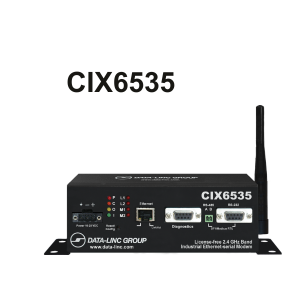
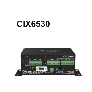
System includes 2.4GHz CIX6535 Protocol Master & CIX6530 Wireless Remote I/O
- I/O device-interface to Ethernet or serial– Ethernet/IP, DF1, Modbus TCP/IP & Modbus RTU protocols
- 12-bit analog resolution
- One CIX6535 supports up to 16 CIX6530 Remotes (384 points)
- Any CIX Remote can RF repeat to other CIX Remotes
- Indicator and signal alerts for communications failure
- 10mile+ (16km) range with LOS( line-of-sight) & Omni antennas
- Up to 256-bit AES encryption
- ARRA compliant*
(CIX6400 System for the 900MHz band is also available)
Contact sales@data-linc.com or call 425-882-2206 for questions, information or to discuss your project. Ready to start your project? Fill up our Request Project Assistance Form, and our team will contact you to assist you in your project.
Product Description
The Wireless Communication Interface Extender (CIX) System by DATA-LINC GROUP
DATA-LINC GROUP’s Wireless Communication Interface Extender (CIX) System is a cost-effective and industrial-grade automation I/O extender that provides direct PLC connection via communication ports to I/O points without complicated PLC programming or proprietary software.
The CIX system utilizes DATA-LINC’s proprietary SRM wireless technology, which offers simplified, low-labor startup, maintenance, and growth for I/O in both the 900 MHz and the 2.4 GHz ISM license-free bands. Wired Remote expansion is also available.
System description:
The “head end” of the CIX system is a dual port CIX6535 Master with an Ethernet and serial port for connection to a PC or PLC. The Ethernet interface supports EtherNet/IP or Modbus TCP/IP and the serial interface supports full duplex DF1 or Modbus RTU protocols.
Each CIX6530 Remote provides 8 discrete inputs, 8 discrete outputs, 4 analog inputs, and 4 analog outputs. A full network with 16 CIX Remotes provides a total of 384 I/O points.
Network features:
Wireless communication is based on DATA-LINC GROUP’s robust & proprietary SRM Smart SpectrumTM FHSS technology, which offers excellent noise immunity and can force output points to a specified value or hold the last value in case of wireless communication loss. The modems come equipped with built-in status lights and event notification alerts that immediately notify users in the event of any loss of communication due to Wi-Fi issues. The system can operate two or more CIX wireless networks in near proximity sharing the same ISM band.
LincViewTM OPC real-time wireless RF network diagnostics are also supported. The system has a range of up to 25 miles with a line-of-sight, even in high-noise environments. The system indicates communication loss due to Wi-Fi issues by a status light and sends out an output bit as an event notification.
Field Configurations:
Field Configuration of each CIX unit is straightforward using DATA-LINC GROUP’s configuration software. DATA-LINC GROUP’s extensive knowledge of PLCs backs the system, making it an excellent option for data acquisition and control applications.
The CIX wireless I/O system is an ideal solution for small or large installations, providing a reliable and cost-effective option with easy scalability. Additionally, the CIX system is ARRA compliant, ensuring that it meets government procurement guidelines.
Downloads
Download Configuration Software Tool for CIX6500 Master Modem
Download Configuration Tool for Remote CIX6500 Modems
CIX/EXR – AOI for I/O Extenders – AOI (Add-On-Instructions) are available for Data-Linc’s I/O extender applications that use Rockwell Logix5000-based controllers. AOI is for Protocol to I/O networks. The AOI is available by request from DATA-LINC technical support. Email:techsupport@data-linc.com .
Specifications
CIX6500 System Specifications
Operating Frequency:
License-free, 2.4 GHz ISM band
Included
CD. Configuration Software, LincViewTM OPC RF Network Management Software, User Manual, Quick Start
Antenna. Test Antenna
0 dB bench test anten
Power Supply
CIX6535 & CIX6530
Operating ranges
System gain. 129 dB
Distance. 10 miles (16 km) LOS with Omni antennas
Transmitter
RF Output Power. 500 mW maximum, 27 dB (programmable steps)
Modulation. Frequency Hopping Spread Spectrum, GFSK
Hop Patterns. 15 (user selectable)
Occupied Bandwidth. 230KHz
Error Correction. 32 bit CRC
RF Encryption. Substitution Dynamic Key, up to 256-bit AES encryption
Receiver
Sensitivity. -105 dBm @ 115.2kbps for BER 10-4
-102 dBm @153.6kbps 10-4 for BER
Selectivity. 40 dB @ fc ±230 KHz and 60dB @ fc ±460 KHz
Operating Environment
Temperature. -40° to 167° F (-40° to 75° C)
Humidity. 0 to 95% non-condensing
Enclosure. 18 gauge steel
Standard. 18-gauge steel
2.47 X 3.70 X 6.4 in. (6.274 X 9.398 X 16.26 cm)
Optional. DIN rail mounting flanges (included)
Shipping Weight. 1.8 lb (0.82 kg)
CIX6535 Master
Included 7′ Cat 5 Cable
Connections
Antenna. Standard thread female SMA for optional external Omni-directional or yagi antennas
external Omni-directional or yagi antennas.
Ethernet. 10/100 Base-T Auto-MDIX
Diagnostic port. RS232 DB9 Female or RS485-2-wire
Power 3-pin pluggable terminal block
Indicators
LAN. Link/Act
RF.Power (P), RF Carrier (C), RF Output (O), RF Input (I)
Mode. M1, M2, L1, L2
Power
Voltage. 10-28 VDC nominal
Current. 160mA idle, 660mA peak on transmit
Operating Environment
Temperature. -40 to 167°F (-40 to 75°C)
Humidity. 0 to 95% non-condensing
CIX6530 Remote
Channel Functions
Analog. 0-20 mA, 4-20mA or 0-10 VDC, 24 VDC max. loop voltage, 12-bit resolution. Self-powered outputs.
Discrete Input. Dry contact closure
Discrete Output. Open collector (sink to ground), 100mA per channel, 12-24VDC
Connections
Antenna. Standard thread female SMA for optional external Omni-directional or yagi antennas
I/O Discrete and Analog. Detachable screw-type terminal blocks Wire size 12-26 AWG
Power. 3-pin pluggable terminal block
Diagnostic port. Standard DB9 Female
EX-Linc. RS232 DB9 Female or RS485 2-wire
Indicators
General. Power (P), RF Carrier (C), RF Input (I), RF Output (O), and Comm Error
Discrete. Activity LED for each discrete I/O
Power
Voltage. 12-28 VDC nominal
Current. 160 mA idle, 660mA peak on transmit
